With the increasing frequency of natural disasters including earthquakes, floods, hurricanes, tornadoes, wildfires and storms with severe lightning, electric utilities worldwide have proactively reinforced their critical infrastructure systems during the cable design phase. This article discusses eight categories of underground power cable components and/or design principles to harden the grid, therefore improving natural disaster resilience.
1. Water-blocking Components.
Water contains oxidizing agents, which trigger the corrosion of metallic shields and conductors. As a result, a “triple-water protection” for underground medium-voltage (MV) cables rated 5 kV to 46 kV has gained popularity in recent years. This is achieved by longitudinally filling the stranded conductor with water-blocking components, applying a semiconductive water-swellable tape underneath or over the neutrals and dusting water-blocking powders under the cable jacket. The powder used in the water-swellabe tapes is also known as Superabsorbent Polymers (SAP), a crosslinked material with thermal and physical stability capable of absorbing ground water up to 150 % of its original weight. [Wire & Cable Technology International Jan/Feb 2017, titled, “Comparative Analysis of Hydrated Gels Formed by Superabsorbent Polymers Commonly Used for Longitudinal Water-blocking of Underground Power Cables”]. The crosslinked gel retains moisture permanently and hinders the penetration of water along the installed cable length. Many water-swellable tapes are now commercially available, but the submarine grades offer the best water-blocking performance due to the amount and the type of SAP powder being used. The water-blocking components under the jacket can also hinder the degree of the neutral corrosions long term.

2. “Dry-Type” Cable Designs.
For critical distribution circuits located within a flood zone or installed within an extremely damp soil under a waterway, MV cables can be enhanced with extra cable components to match dry-type underground high-voltage (HV) transmission cables. For example, a conductor tape not only prevents the conductor shield from falling into the interstices of a large stranded conductor during extrusion or operation but also reduces the operating electrical stresses, especially at higher distribution voltages such as 35 kV or 46 kV. Water-swellable tapes under and over the neutrals, which were mentioned in the previous section, are essential for dry-type MV cables. Aluminum or copper foil laminated shielding tapes expand the metallic cross-sectional area to boost the short circuit performance. Up to 35% extra short circuit current carrying capacity can be accomplished compared to a MV construction with concentric neutrals only. The composite shielding tape features a high-temperature hotmelt adhesive coating on one side to physically bond the tape to the inside of the overlaying jacket, which eliminates air gaps and impedes longitudinal water intrusion in case of a jacket puncture.

3. Abuse-Resistant Cable Jacket Alternatives.
MV cable jackets are commonly made with a thermoplastic linear low-density polyethylene (LLDPE), but demand has increased for more Abuse-Resistant Jacketing Alternatives in the past decade. Three popular options include Crosslinked Polyethylene (XLPE), Polypropylene (PP) and High-Density Polyethylene (HDPE) compounds. These three materials exhibit a higher softening temperature and enhanced physical properties when compared to LLDPE, which improves the thermal, mechanical and chemical resistance of this overall barrier. Furthermore, it enables the cable core to operate at elevated temperatures and to better withstand harsh environmental elements during a natural disaster. In the case of a 25 kV, 1/0 AWG aluminum conductor with 100% or 260 mil of Tree-Retardant XLPE insulation, more than a 40% increase in short circuit capacity can be obtained by changing the LLDPE jacket to XLPE. This is because XLPE has a high transient temperature rated at 350oC compared to 200oC for a LLDPE jacketed cable per ICEA P-45-482. These robust jackets also demonstrate a lower moisture vapor transmission rate enabling this physical barrier to sustain wet exposure under an extreme temperature fluctuation because of seasonal weather events such as ice storms and heat waves.
4. Low-Friction Jacketing Materials.
For both utility and commercial projects, many requirements call for a low-friction jacket. MV cables are pulled into either a PVC or a HDPE conduit in the field and in some instances long cable routes may contain several challenging bends. Southwire Company’s patented Powerglide® LLDPE and SIMpull® PVC technology features a physically imbedded low-friction additive that generates a surface with a permanently reduced coefficient of friction (COF). Because the lubricating agent is dispersed evenly within the compound prior to jacket extrusion, the COF remains consistent throughout the entire on-site cable pull. This is a marked improvement over pulling lube application in the field. Additionally, the inherent friction-reduction minimizes potential jacket tears during cable pulls, thus extending the physical protection during any future major natural disturbance.
5. High-Strength Ripcords.
Cables can also be incorporated with two ripcords laid about 180 deg apart under the jacket. The ripcord contains a high breaking strength twisted aramid filament with an extremely low elongation. This design allows crews to safely and efficiently pull and cut through the water-swellable tape and/or mylar separator as well as the jacket during cable preparation for splices and terminations. The use of ripcords to cut jackets also reduces jacket rips and potential injuries from using sharp cutting tools in the field.
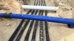
6. Cable-in-Conduits.
Utilities or contractors can pre-install any underground cable in a durable High-Density Polyethylene (HDPE) conduit to avoid the pulling of cables into a pipe in the field. This pre-installed cable assembly, known as Cable-in-Conduit (CIC) can be manufactured by continuously extruding an impact-resistant HDPE conduit over a single cable or a parallel cable assembly. For MV distribution cables, three-phase conductors are laid in parallel within an extruded conduit to prepare them for on-site installation. The cables are pre-lubricated with a low friction pulling agent to prevent the cables from adhering to the inside of the conduit wall and to allow for easy future replacement. CIC applications meet NEMA TC-7, UL-1990, as well as the National Electrical Codes (NEC) for commercial, residential and utility applications. The finished conduit passes crush and impact tests and is rated for direct burial or encasement in concrete. The CIC option not only saves labor and installation time and reduces the total cost of the project, but it also creates an extra layer of mechanical protection for the cables. The non-metallic pipe is hydrophobic with a very low degree of moisture absorption. HDPE pipes will minimize damage from accidental dig-ins, future utility repair work or collapsing of structures above ground during severe weather events.

7. Flame-Retardant Cable Designs.
For highly populated areas, electric utilities install many distribution systems in a three-phase underground network. Compact vaults or manholes are often located below congested downtown streets. Therefore, the safety and reliability of the low voltage (LV) cable system (600V or 2kV) is of critical importance. Such heavy-duty network cables are operated to meet the growing demand of electrical loads. Consequently, secondary network cables are designed specifically to withstand high temperatures, moisture ingress and chemical exposure. They are also flame retardant and inherently abuse- and abrasion resistant. The LV network cables can be insulated with a leaded or a lead-free thermoset Ethylene Propylene Rubber (EPR) and/or the broad Ethylene-Alkene Copolymer (EAM) chemical family. The overall jacket can be manufactured with either a thermoset flame-retardant Low Smoke Zero Halogen (LSZH) or a crosslinked Chlorinated Polyethylene (CPE) material. The jacket is heavily filled with flame-retardant additives, which hampers flame propagation and reduces the amount of smoke in the event of a fire. Each cable design meets the vertical tray flame test per IEEE 1202 (FT4). The EPR/LSZH LV network cables are one of the most sustainable LV cable designs to deliver grid resiliency in a congested metropolitan area.

8. Shielding Upgrades.
For transmission substations containing a variety of extra high-voltage (EHV) equipment (230 kV and above), significant sources of electromagnetic interference (EMI) are present. EMI may originate from capacitor bank switching events, disconnect switching operation, lightning, power-frequency high-current faults, SF6 equipment failures and EMF sources within power cable circuits. Consequently, electric utilities install LV control and power cables with shields in HV and EHV substations to mitigate EMI. Many factors related to the substation designs will dictate the magnitude of EMI and the degree of transient protection. For example, the use of shield grounding at single end versus both ends, location and types of surge protection devices, cable routing, segregation between LV vs. MV/HV/EHV cables, and the installation of Ground Continuity Conductors (GCC) close to the LV control and power cables play a significant role in EMI mitigation. In addition to the system designs, one can also augment the EMI protection by upgrading the shielding material within the cables. The EMI shielding efficiency depends upon the electrical conductivity, coverage of the cable core, shielding diameter and thickness of the shield. Doubling the number of helically applied copper tape shield with a greater thickness and a higher percentage of overlap will improve the EMI shielding effectiveness compared to a thinner and single-wrapped tape shield. Because the shield in LV cables is not rated to carry power-frequency fault currents, a crew should install one or more grounding conductors near each cable circuit.

In conclusion, natural disasters and weather events are inevitable. It is our industry’s responsibility to continue to innovate and collaborate among raw material producers, wire and cable manufacturers and electric utilities to design, select and upgrade the cable systems accordingly depending on the geography and the type of the grid. Utilities can harden their systems and delay or avoid premature cable failures by using one or more of the eight design recommendations highlighted in this article.
Dr. Hawig holds a Ph.D. degree in Polymer Engineering from Case Western Reserve University in Cleveland, Ohio and she co-authored sixteen technical articles in ten peer-reviewed journals in the field of advanced polymer materials and is the inventor for several US patents. She was also the recipient of the Power Systems & Solutions Engineering Award at Southwire in 2018 and has been serving on the Neetrac (National Electric Energy Testing, Research & Applications Center) Management board since 2015.
Sponsored By: