voltage-drop test allows one to stress the circuit to see if it's capable of supporting the intended function (operating the RPSD system).")
Content brought to you by Motor Age. To subscribe, click here.
What You Will Learn:
• You can still evaluate a circuit's functionality, even if it is non-functional
• Finding the root cause of why something doesn't work is what we should always be in pursuit of
• A wiring diagram is your greatest asset when it comes to electrical system diagnosis
As automotive technicians in today's world, we are faced with hundreds (if not thousands) of electrical challenges each year. Of course, some faults are more difficult to find than others, and we have all been down the path where we get our butts handed to us. But maximizing our proficiency through practice will lead to maximizing accuracy and efficiency.
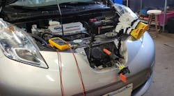
Now, imagine you’re not a factory-trained technician addressing the same vehicles frequently or a technician working at an independent who has many times gone the extra mile to locate information and the correct tooling. Instead, picture yourself as a technician challenged with faulted mobility-vehicles for the physically disabled, seeing many different new vehicles and having to seamlessly mate state-of-the-art mobility-assist systems with today's latest factory-installed technologies. This is what my good friend, Bob Leonard, calls a typical workday, as he is a technician for Mobility Works, a company dedicated to enabling freedom, with stores across the country (Figure 1).

On this particular day, Bob was faced with a difficult task. It was the result of a single diagnostic test he performed that led down a path of extensive disassembly, but with confidence that he was on the correct path. I'm going to show you how he did it and why he believes in continuous training in and out of the shop.
The task at hand
Like any other day at the shop, Bob was presented with a vehicle with the complaint that some of the mobility-assist accessories were not functioning. This is more important than just a malfunctioning creature-comfort, as the accessories are not just simple “conveniences” but allow those that are physically challenged to be more independent and able to accomplish their day. What seems minor to those of us physically capable can be a huge deal to a physically disabled person.
Bob was issued a repair order for a 2013 Honda Odyssey with the complaint of the right-side power sliding door (RPSD) to be inoperable. This is particularly important because without the functionality of the door in proper working order, the Ramp and the Kneel-system both will not function. Knowing what questions to ask allows one to focus their diagnostic approach in the correct area. So, the initial question then becomes:
Where does one start their diagnostic approach on a vehicle like this one?
Like many of today's vehicles, even this 2013 minivan had dozens of computers that communicate on networks to accomplish tasks. It has complex systems with many intricacies and components that must function together in unison, like a well-choreographed ballet. Any number of individual faults can cause symptoms like the one described above. It's our job as technicians to get to the root cause of the symptom, but how?
If the OE-side of this monstrosity isn’t difficult enough to decipher, now Bob has to wonder if the fault has something to do with the “conversion-side” of the system. After all, I'm sure many of you experienced diagnostic technicians will agree that man-made faults are some of the most difficult to uncover at times. Stepping back from the vehicle and evaluating the situation, Bob decided to use logic instead of guess work. This employed logic includes a full understanding of the system(s) he is addressing, as well as the functionality of the components that make up that system. Here is what Bob knows to be factual:
All the players on the team
Power Sliding-Door, Ramp, and Kneel systems are managed by the electronic control system.
Can be activated via key FOB, interior mechanical switches, or touch-screen interface display.
The Ramp/Kneel system will not function without proper door position feedback.
The Conversion Module drives the Ramp/Kneel systems but is initiated by the OEM-system.
As noted in the bullets above, it is quite clear that the "conversion-systems' components" have to work in tandem with the OEM-system and its components. So, knowing what we now know, the question then becomes: Is the fault on the OEM-side or the Conversion-side?
With the engineering of the mobility-assist systems, included was a procedure to temporarily bypass the conversion system. What this did for Bob was allow him to remove the conversion system from the equation to then determine if the operation of the right power sliding door (RPSD) was restored. Knowing already that both the Ramp and the Kneel-features would not function without the proper operation and position feedback of the RPSD, Bob initially focused his efforts on the malfunctioning RPSD only.
The procedure was carried out and the conversion system was bypassed, effectively eliminating it as the system containing the fault. The RPSD still did not function. Bob could now focus his efforts on uncovering a fault housed within the OEM-side of the vehicle. The point is that discovering what simply cannot be leaves only the possibilities to focus on. Splitting the system in this fashion eliminates wasted time and effort.
Bob then began to troubleshoot the OEM-side of the power sliding door system as if the van had no conversion system whatsoever. With that came the scan tool. Bob performed a full-vehicle scan and discovered no DTCs or any lack in communication between the scan tool and the RPSD control unit. Bob was forced to follow factory troubleshooting procedures with only the symptom as a reference. Although leery of the prescribed repair, the factory flowchart eventually advised Bob to replace the RPSD Control unit with a "known-good" controller. This, of course, isn't typically an option, especially in the aftermarket world. Reluctantly, and without confidence, Bob ordered himself a brand-new Honda factory RSPD control unit and installed it, per factory installation procedure. As expected, the fault remained unchanged, and it was back to the drawing board for Bob.
Disappointment becomes the driving force
The problem with following troubleshooting flow charts is that they don't always lead us to the root cause of the fault. They simply were not written to accommodate you, the technician, addressing the vehicle in your work bay. They were written to assist the average factory-trained technician with the faulted vehicle (still under warranty policy) with the most probable cause and aid to rectify the fault as inexpensively as possible.
For instance, when the flowchart calls to condemn an ECU, one of the final few statements prescribed before condemnation is to verify connector/terminal integrity, as well as adequate voltage/ground supply. With the connector separated from the ECU, the technician is instructed to make the measurements with the digital volt/ohm meter (DVOM). This is exactly what Bob did, and the outcome of the test indicated no outside circuit fault present. This, of course, led to the replacement of the RPSD control unit, per flowchart instructions.
What this flow chart failed to address is the fact that available voltage or adequate ground supply is not a valid test. If the results of the test indicate insufficient supply then, of course, "bad" is bad. But an open-circuit test like that is not an accurate stressor of the circuit being tested. A test conducted in this matter can only truly indicate the continuity of the circuit. However, it cannot determine the circuit’s ability to support current flow.
It goes back to the old anecdote regarding the resistance of a copper cable with 100 strands of wire composing it. If one were to sever 99 strands of the cable, the resistance of the cable would still measure the same (as before the cable was tampered with). However, if one were to then use that same single-strand cable to complete a starter motor supply circuit, they would realize quickly that the cable is not cable of supporting the required current to operate the starter motor. They would likely discover how that cable makes a handy fusible link as the insulation vaporizes to smoke!
Unfortunately, Bob realized the hard way that the prescribed test lacked the information he needed to make an accurate diagnosis. He had missed something, and it had just hit him like a ton of bricks. He had now realized that the test he performed ddi not test the system under normal operating conditions. To accurately test the system’s voltage and ground supply integrity meant to test it when the circuit is functioning. The problem is—the circuit doesn’t function!

The loaded voltage drop test
This all relates to the principles described by Ohm's Law. As current flow increases in a circuit, so too does the voltage dropped across a resistor. In other words, if there is no current flow present, the voltage will not be dropped across any resistor—either intended loads or unwanted resistance—in a circuit. To conduct this test means to have the circuit energized or functioning.
This power sliding door system doesn’t respond at all to any switched-input or command, so the circuit has no current flow within it. Therefore, a voltage drop test cannot be conducted. However, if one were to manually load the circuit, a test for true circuit integrity can accurately be determined, and this may uncover the reason the system is not functioning. Game on!
Bob now knows what he has to do, so he chose a load similar in current consumption as the circuit to be tested. As can be seen, the WHITE wire leading from the under-dash fuse block supplies voltage to the RPSD control unit at terminal B1 (Figure 2). Although it cannot be seen in the picture, the voltage originates from the under-hood fuse block across a 10A fuse. Bob chose an 1157 bulb to see if he could force the fault to the surface. If this circuit managed a lot more current (like that of a starter motor), the test-load would have to be heavier to stress the circuit’s wiring properly, as this test is intended to do.
With the connector removed from the RPSD Control Unit, the 1157 lightbulb was substituted (as the load) and was supplied a known-good ground to allow the bulb to operate. This test used the existing RPSD control unit's voltage supply circuit to energize the light bulb. As the bulb illuminated (dimly, at that) a voltage-drop measurement was taken across it. Knowing that this bulb should be the only load in this series circuit, one would expect the bulb to drop all of the voltage (approximately 12.5V) and illuminate brilliantly if the circuit is functioning as designed. However, this bulb is only dropping 2.5V. The result of the test tells us a few things:
- 10V is being dropped somewhere before the bulb (in the power supply circuit).
- Further disassembly is required to pinpoint the source of the voltage drop.
- The wiring diagram will help determine the most logical place to begin disassembly.

Destined for disassembly
The last thing a diagnostician wants to do is disassemble anything for testing. That is, of course, unless it is justified. The results of the loaded voltage drop test Bob conducted conclusively pointed to a significant high-resistance fault on the voltage supply side of the system. More importantly, there is no doubt where he has to invest time to disassemble for further testing (no wasted time, no guesswork). The significance is Bob will not have to backpedal, as he is assured to find the source of the fault if he simply trusts and follows the test result.
However, an excellent strategy he will employ will be to reference the wiring diagram to determine the component locations. Using this information, along with how the vehicle has been altered to accommodate the mobility-assist features, should allow him to focus his further efforts and avoid wasted time. This is working smarter, not harder.
The modifications to the original vehicle wiring harness take place below the floor of the second-row seating. The voltage source circuit in question comes from the passenger side kick panel. The RPSD control unit is located in the right-rear quarter panel. Bob chose to remove the interior second-row floor to inspect the harness where the mating of the original and conversion-harness are made (Figure 3). Upon accessing the harness, another unexpected discovery was made. The vehicle appears to be taking on water (Figure 4).

The wires making up the harness were separated to allow Bob to inspect the circuit in question. To his delight, an ugly GREEN corroded section of wire was exposed due to its submersion in the water-logged floor. The corroded wire was exposed because the insulation was compromised during the installation process. The wire appeared to be sliced by either a razor blade or some other sharp object (Figure 5).
Bob “jumpered-voltage” past the GREEN-spot in the harness and proved the system to function before making the necessary repairs. This is never a bad idea, as sometimes more than one fault exists simultaneously. It is better to know ahead of time than to commit to repairing a single fault, only leading to a partial fix of the symptom.
Reflecting on what happened makes it quite simple to understand if we revisit the original wiring diagram (Figure 6). The RED “X” is where he found the voltage drop. By substituting a bulb (so he could energize the circuit), it was seen that the bulb dropped only 2.5V (leaving 10V being dropped/wasted elsewhere in the supply-side of the circuit). Thinking of it like this may simplify further: The RPSD control unit could not function because it only had 2.5V supplied to it to function with.
Bob discovered that a door seal was displaced, which caused the water intrusion. It was properly mated to the body of the van and the damaged section of wire was isolated, replaced, and properly sealed. The existing wire harness was placed in conduit, properly routed, and secured to prevent future issues. The van’s conversion system was fully estored to proper functionality, and the customer left happy.

Mastering the basics
We are all faced with challenges each day. Some of the challenges can really “eat our lunch,” and that’s never a pleasant experience. But learning from these situations and making adjustments to our systematic approach can limit these events. This particular vehicle has hundreds of circuits, and a symptom like the one experienced could be caused by a root-cause fault located anywhere between the two bumpers, the floor, and the roof! Understanding principles like Ohm’s Law and the testing techniques developed around them (like the loaded voltage-drop test) prevented Bob from going off into the weeds and unnecessarily disassembling other areas of the vehicle. Learning to incorporate these techniques and mastering them is not only suggested but is what it takes to stay in the game long-term and come out on top successfully—every time!